Hi
when you have a moment please "vote" for yourself on the new poll if you have completed your pedal so that we can get an idea of whats going on.
please do not vote for people other than yourself.
Sunday, March 23, 2008
Friday, March 21, 2008
Led Wiring DIagram
Hi
A lot of people are reporting not getting an email i sent out on march 20. So if you did not get it please read all the recent updates on this site. The LED is here now and you can call me to arrange meeting up. I live near sherbrooke or st laurent metro and i am at concordia everyday in the week as well.
and so...
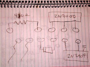
Here is some info on how you will wire the LED to get it red in one mode and green in the other.
You may or may not have already put 2 wires in the holes i have circled and labelled A and B. If you haven't you should do so now.
Wire A will go to the Middle pin on the LED.
Wire B will go to the middle pole on the unused side of your switch.

Now, the final touch is to connect each of the outer pins on the LED to each of the outer pins on the same side of the switch that wire B is connected to.
and thats all.
if you reverse left and right all that will change is which position of the switch is which color. it will work either way.
A lot of people are reporting not getting an email i sent out on march 20. So if you did not get it please read all the recent updates on this site. The LED is here now and you can call me to arrange meeting up. I live near sherbrooke or st laurent metro and i am at concordia everyday in the week as well.
and so...
Here is some info on how you will wire the LED to get it red in one mode and green in the other.
You may or may not have already put 2 wires in the holes i have circled and labelled A and B. If you haven't you should do so now.
Wire A will go to the Middle pin on the LED.
Wire B will go to the middle pole on the unused side of your switch.
Now, the final touch is to connect each of the outer pins on the LED to each of the outer pins on the same side of the switch that wire B is connected to.
and thats all.
if you reverse left and right all that will change is which position of the switch is which color. it will work either way.
Thursday, March 20, 2008
Bypass / offboard wiring
for the info regarding the wiring of the switch and jacks, please refer to:
http://tonepad.com/getFileInfo.asp?id=76
Use offboard wiring #3 in that document.
http://tonepad.com/getFileInfo.asp?id=76
Use offboard wiring #3 in that document.
Tuesday, March 18, 2008
Lost & Found

2 pairs of wire strippers were left at the pines. They appear below. I have them at my house now and also someone seems to have perhaps left with one of my third hands. If these are your tools or you have mine please let me know.
Bypass Component Orientation
Hi
I am aware there is some confusion about the orientation of the bypass components
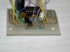
these pictures should help clarify
Where there is an led on my board solder 2 wires in preparation for your LED.
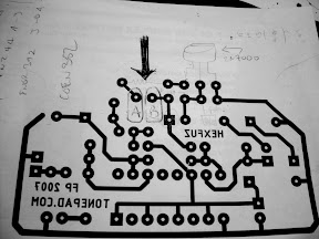
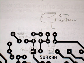
The flat side of the 2n7000 and 2n3904 (or 2n2222) face the closest edge
also there SHOULD be 2 holes on your board that do not have copper traces on the bottom. these will be explained later when you get the LED. we had to add an extra diode (which i will also supply with the LED) to suppress teh large amounts of noise that this pedal generates when there is no input. if you are confused dont worry it will work fine!
Also in one diagram i circled the square pad that is the entry for the 9V.
The diode is POLARIZED please take note which way you put it on the board. look at the pencil diagram to see which side the stripe is on. you should be able to see the stripe on the diode as well. Just match them up and you will be fine.
FINALLY i know some people took pictures. if you would like to share them with me it would be appreciated and i would like to post one or 2 on the site.
I am aware there is some confusion about the orientation of the bypass components
these pictures should help clarify
Where there is an led on my board solder 2 wires in preparation for your LED.
The flat side of the 2n7000 and 2n3904 (or 2n2222) face the closest edge
also there SHOULD be 2 holes on your board that do not have copper traces on the bottom. these will be explained later when you get the LED. we had to add an extra diode (which i will also supply with the LED) to suppress teh large amounts of noise that this pedal generates when there is no input. if you are confused dont worry it will work fine!
Also in one diagram i circled the square pad that is the entry for the 9V.
The diode is POLARIZED please take note which way you put it on the board. look at the pencil diagram to see which side the stripe is on. you should be able to see the stripe on the diode as well. Just match them up and you will be fine.
FINALLY i know some people took pictures. if you would like to share them with me it would be appreciated and i would like to post one or 2 on the site.
Saturday, March 1, 2008
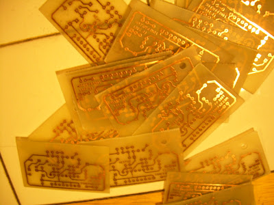
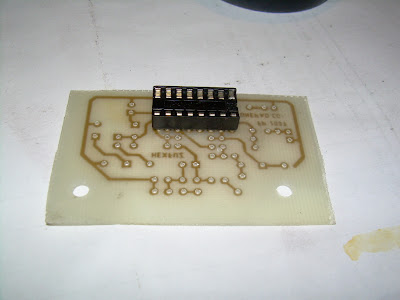
pcbs in progress...
just to update, we have etched the pcbs for the first build. they are not all drilled yet but here are some pics from the process.


Subscribe to:
Comments (Atom)