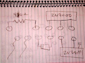
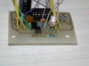
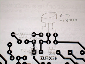
I am aware there is some confusion about the orientation of the bypass components
these pictures should help clarify
Where there is an led on my board solder 2 wires in preparation for your LED.
The flat side of the 2n7000 and 2n3904 (or 2n2222) face the closest edge
also there SHOULD be 2 holes on your board that do not have copper traces on the bottom. these will be explained later when you get the LED. we had to add an extra diode (which i will also supply with the LED) to suppress teh large amounts of noise that this pedal generates when there is no input. if you are confused dont worry it will work fine!
Also in one diagram i circled the square pad that is the entry for the 9V.
The diode is POLARIZED please take note which way you put it on the board. look at the pencil diagram to see which side the stripe is on. you should be able to see the stripe on the diode as well. Just match them up and you will be fine.
FINALLY i know some people took pictures. if you would like to share them with me it would be appreciated and i would like to post one or 2 on the site.


No comments:
Post a Comment