Posting Permission

If anyone who wants posting permission on this site please email me mtl.asm@gmail.com and i will add you

thanks

scott.

Thursday, February 12, 2009

Some Photos From Feb 8th

Here are some photos of the Feb 8th meeting.


Tuesday, February 10, 2009

Optical Synthesizer Documentation

This post will contain all documentation relating to the optical synthesizer project.

The schematic, layout and the whiteboard hardware wiring description are available here.

There is one item missing from the whiteboard list. The black lead coming off the battery snap should go to the "G" terminal on the DC Jack.

I have added some hints on how to make the probe assemblies for those that are not that far along. Same location, "MakeProbesOne" and "MakeProbesTwo".

Obscene Fuzz Documentation

This post contains all documentation related to the fuzz project.

Schematic, layout and hardware wiring diagrams available here.

Note 1: i have made a very slight revision to this design which involves adding one more capacitor. Both schematics are available at the above link.

Note 2: leds could be used instead of 1n914's to increase the maximum output level or replace 1 1n914 with 2 in series etc...

There are now more sound samples available here and i also have a few available for sale for $35.

Sunday, February 8, 2009

Trouble Shooting...

Hi

Here are some specific insights into the synthesizer board.

1) Jacks

First check that you have the output in the correct jack. Remember we called one TRS and one NC-TS. The TRS is the output. There does not have to be anythign connected to the NC-TS for the unit to operate.

2) Voltages

Here are some DC measurements you should find on the ICS.

PIC

The pic is the MIDDLE IC.

Pin 1 of the MCU (PIC12F683) Should have 5 volts. If you are measuring something higher disconnect power immediately. Verify that R18 is installed correctly and that the Zener Diode D2 is oriented in the correct position. One side of R18 should show 9 volts and the other 5 volts.

Pin 8 of the MCU is ground. All other pins may vary during operation.

TLC2272

This is the op amp labeled TLC272 on your handout. Im not sure why it dosnt say 2272. Pin 8 should show 9 volts. Pin 4, 5, 6 and 7 should show 0 volts. Pin 3 should show around 2.1 volts.

RC4580

This one is labeled TL072 on the layout.... Pin 8 is 9 volts. Pin 4 should show 0 volts. Pin 3 and 5 should show around 4.5 volts.


3) General Signal Flow

If you have an oscilloscope you can try to follow the signal incase it is being generated but not making it through the volume modulation.

Power on the instrument and hit the red button once to advance it into the sound generating subroutine. measure the output of pin 5 6 or 7. you should see square waves with 5v peak to peak. If you dont see any output on any of these pins keep depressing the red button and measuring. If no signal is obtained there is a flaw with the mcu itself.

If you see some squares there move on to pin 7 of the RC4580. The output of this should show (with some DC offset) a signal of somethign in the order of 2 volts peak to peak. If you see nothing on your screen make sure you have compensated for the dc offset either by adjusting the vertical position or switching to AC coupling.

Still nothing? there is problem with this op amp. Double check the power on the pins mentioned above.

If you have something on pin 7 check on the tip of the NC TS, you should see the same thing there. And accordingly on the switch side of the NC TS.

Now check the output of the 4580 on pin 1. If you have something here but no output on the jack then double check that you have "out" on the pcb wired to the TIP of the TRS.

4) Probe Response

my probes do nothing

Disconnect the probe assembly from the unit. Set your multimeter to a 200k or 2M ohm range. You may have to remove the hood from the connector to verify you are measuring the correct pins, but in general you should read a resistance that varies from about 500 ohms to over 100k across the red and black wire pairs. ie the resistance across each probe should vary when it is exposed to light. If the resistance is infinite or you measure open circuit and see no variation then either there is a disconnect at the photocell or a broken connection at the plug. Make sure the black and red wires are securely soldered onto the plug pins by gently tugging them. If you measure a very low resistance that dosnt vary then the red and black wires are shorting somewhere.


the change in response caused by the pots is radical, abrupt and does not vary over the whole rotation of the pot

De solder the wire on the two outer pins of the pot and exchange them. ie the wire that was going to the left side now goes to right and vice versa.


I will add more later. Please post in reply or email me if you have specific questions.

Sunday, January 18, 2009

Specifics of Jan25/Feb8

The address for the workshop is 5832 Blvd St Laurent.

The time of the sessions will run from 5-9 pm on both Jan 25th and Feb 8th.

If you have a soldering iron/wire snips/strippers/needlenose pliers please bring them along. (If you dont have, dont worry).

Please feel free to bring some music/munchables as well.

email mtl.asm@gmail.com if you have questions

Saturday, January 3, 2009

Details of next workshop Jan 25th 2009

Hi

So there will be another workshop on January 25th (which is a sunday). It will be in a space in the mile end area.

More importantly here's what i am offering up. The main project is something like an optically (light) controlled synth. I tried to push it a bit further then the somewhat limited 555 synths that are all over the place. I put some videos up so you can see. Right now i have about 5 or 6 sounds programmed in but i am working on more now that everything is functioning well otherwise. So please take look at the vids. There is a dynamic sensor (volume) and a pitch sensor. The sensitivity of each probe is adjustable via 2 pots. Then there is a button which may be hard to see in the first video but it cycles through the different sounds. (dont worry you get a case, i just haven't put mine in one yet)


I will also offer a very simple project with few parts that is an extremely fuzzy distortion. I made a short clip of one i made, you cannot see the board in the video but there is only 10 or 12 parts on it. It would be a good project if you just want to get your feet wet.


The synth project is $50 and the fuzz is $40 for everything you need. If you would like to participate i need to receive confirmation asap and payment by January 16th at the latest. Im arranging a second date as well which will likely be feb 8th (exactly 2 weeks later) so that you dont have to rush to finish in one day.

In terms of tools i have some extra soldering irons and some other basic things so if you dont have much/any dont worry there will be something available, but please try to bring your own if you do have them.

Also, if you have come to a previous workshop but you are not finished/you are missing or have lost parts etc... please feel free to come to this and finish up but please let me know in advance what you need or where your at.

You can contact me at

mtl.asm@gmail.com

Thanks

scott.

Thursday, November 13, 2008

Using epoxy resin to coat pedals

Hey all,
I've been experementing with new ways to protect paintjobs, seeing how pedals get kicked around and generally brutalized. Acrylic laquer wasn't cutting it. enamel was a bit better but sometimes it's nice to find alternates to spraycans.

I found epoxy resin at Omer DeSerres, the art store around town. it's their own vitra-laque brand (and there are other brands too). it's pretty expensive. around $30 for the kit of two bottles (epoxy + hardener) but I bit the bullet and gave some a try. mixed up a small batch and oozed it on a boost I just built.


the result is really fantastic! it does take around 2 days to harden enough to call it done, but it feels far stronger than anything I've tried. it feels like glass to the touch and shines like it too, and feels like it can take a beating. anyways if you can afford it, I reccomend it. there's probably 6-8 pedals worth of epoxy in the vitra-laque kit.

Wednesday, October 8, 2008

xxx photos of finished pedals? xxx


....i finally got around to building the red llama clone from the first workshop.....sounds real nice......would love to see what other folks have been doing.....would be nice to have sound clips somewhere as well to listen to these things......

Saturday, July 19, 2008

workshop # 1 pictures and more..

Right, I'm going to give this blog thing a shot. A couple people have expressed interest in a couple of the pedals that were brought-in! The first of which was a feedback looper, the bypass looper that put all of the effects in its loop into crazy oscillating madness! It's a fairly simple project and doesnt involve any circuitry! If you've managed with the fuzz project or the ringmod, this will be a piece of cake! It's just a couple switches, wires, a potentiometer (and knob) and the enclosure of course. It's a great little box you can quickly build in-between workshops and have fun decorating!

Instructions for it can be found in this forum thread below. If you have any questions, you can email me as well.

thread on experementalistsanonymous.com

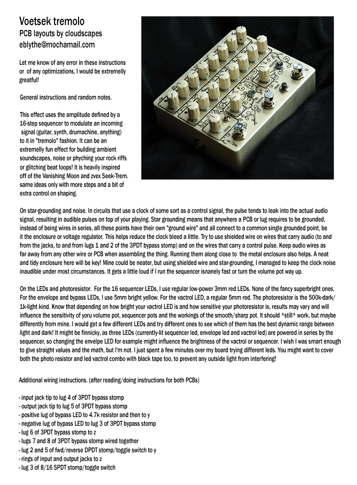
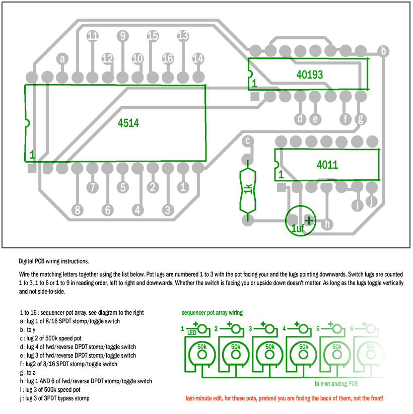
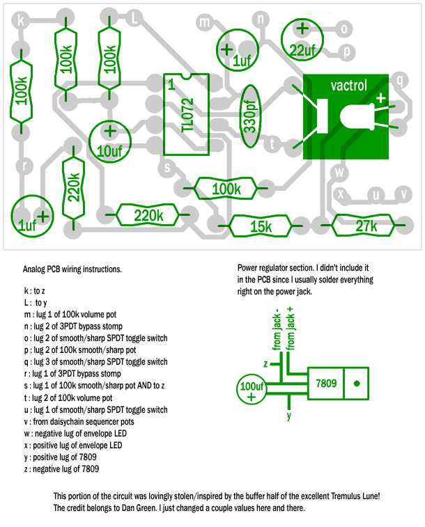
A couple other people have also expressed interest in that crazy 20-knob sequenced tremolo-thing! It should be considered more advanced, but I think I've compiled some good instructions. I should also warn that it doesnt work perfectly. There isa bit of ticking noise when its playing, and some values could be optimized, but at least it works! All parts can be found at Addisons. Again, if there are any questions abotu it, email me and I will do my best to answer!

voetsek_instructions_1.gif
voetsek_instructions_2.gif
voetsek_instructions_3.gif
voetsek_tremolo_diy_instructions.zip

Here are some photos from the first workshop


Friday, July 18, 2008

fuzz face details

Hi

The following may help you complete your fuzz face.

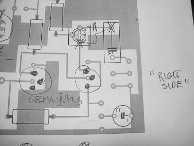
First off as most people know from coming out last week, one of the transistors on the layout sheet is facing the wrong way. It is the p channel fet that was given out on that sunday. the orientation should be rotated 180 degrees. see the photos below.


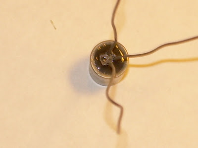
Next up, germanium orientation. If you look closely at te bottom of the germanium transistors youll see the leads are not really in a straight row. instead they form abit of a triangle.


flip the board so that teh component side is facing you.

rotate the board so that the pots are in what you would consider the "lower right corner".

the input jack should be on the left and output on the right.

now populate the BOTTOM 3 PINS of the socket with germanium transistor such that the MIDDLE LEAD is closest to the RIGHT SIDE off the board. The orientation is the same for both germaniums.


Before the next step you may want to test your pedal to see how you like it. I spent some time with Maria's pedal and found the output was not that high and sort of nasaly sounding. The current gain of the transistors we have is not quite as high as the ones specified. but luckily it is easy to compensate. heres how.

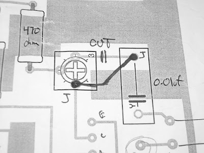
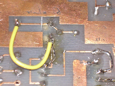
Instead of a fine tuning mod we will use the trim pot as a large gain adjustment. Simply cut the trace from the output cap to the trim pot and solder a wire from the cap to the other side of the trim pot. Look at the photos.


Heres the mod on Maria's. ONLY AD THE YELLOW WIRE. teh other wires were added to replace lifted pads and may not be required. (definitely not required for the "mod")


Now play with the pot until your desired output level is achieved.

IF you still have questions please either make a post or make a comment. if you are confused it is likely other people will be too so it is more useful to ask in a forum accessible by everyone as opposed to through email. THANKS

Sunday, May 11, 2008

workshop #2

workshop #2 is full!

if you have booked a spot, we will be in touch with you soon about payments/details.

thanks!

do not hesitate to ask if you are interested in future workshops (there will be more!) or have any questions, comments, etc...

talk soon.

tyler and scott.

tylerbcrawford atttt gmail dot com

Friday, April 4, 2008

The magical missing diode

HI


the following information is in regards to the last diode which populates the added holes with no traces.

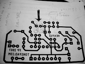
look at the picture


what a mess but it should help . look where it says "hexfuz" backwards. place the end of the diode with the stripe (cathode) into one of the holes with no trace and teh other end (anode) into the unpopulated hole that should be above the "z". if you can make out the semi retarded red diode in the picture it shows correct orientation.

NOW the last wire that you didnt connect on your stomp switch goes into the other hole with no trace (labeled MILB on the diagram). solder the anode (striped end) of the diode to the new wire under the board to simulate a trace. this is depicted in my diagram by a neon green "u" shaped blob.


congratulations thats the end of this procedure.

Sunday, March 23, 2008

Completion....

Hi

when you have a moment please "vote" for yourself on the new poll if you have completed your pedal so that we can get an idea of whats going on.


please do not vote for people other than yourself.

Friday, March 21, 2008

Led Wiring DIagram

Hi

A lot of people are reporting not getting an email i sent out on march 20. So if you did not get it please read all the recent updates on this site. The LED is here now and you can call me to arrange meeting up. I live near sherbrooke or st laurent metro and i am at concordia everyday in the week as well.


and so...


Here is some info on how you will wire the LED to get it red in one mode and green in the other.

You may or may not have already put 2 wires in the holes i have circled and labelled A and B. If you haven't you should do so now.


Wire A will go to the Middle pin on the LED.

Wire B will go to the middle pole on the unused side of your switch.


Now, the final touch is to connect each of the outer pins on the LED to each of the outer pins on the same side of the switch that wire B is connected to.

and thats all.

if you reverse left and right all that will change is which position of the switch is which color. it will work either way.

Thursday, March 20, 2008

Bypass / offboard wiring

for the info regarding the wiring of the switch and jacks, please refer to:

http://tonepad.com/getFileInfo.asp?id=76

Use offboard wiring #3 in that document.

Tuesday, March 18, 2008

Lost & Found


2 pairs of wire strippers were left at the pines. They appear below. I have them at my house now and also someone seems to have perhaps left with one of my third hands. If these are your tools or you have mine please let me know.

Bypass Component Orientation

Hi

I am aware there is some confusion about the orientation of the bypass components

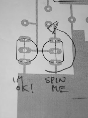
these pictures should help clarify

Where there is an led on my board solder 2 wires in preparation for your LED.

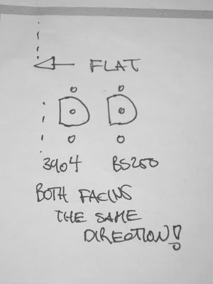
The flat side of the 2n7000 and 2n3904 (or 2n2222) face the closest edge

also there SHOULD be 2 holes on your board that do not have copper traces on the bottom. these will be explained later when you get the LED. we had to add an extra diode (which i will also supply with the LED) to suppress teh large amounts of noise that this pedal generates when there is no input. if you are confused dont worry it will work fine!

Also in one diagram i circled the square pad that is the entry for the 9V.

The diode is POLARIZED please take note which way you put it on the board. look at the pencil diagram to see which side the stripe is on. you should be able to see the stripe on the diode as well. Just match them up and you will be fine.

FINALLY i know some people took pictures. if you would like to share them with me it would be appreciated and i would like to post one or 2 on the site.


Saturday, March 1, 2008

pcbs in progress...

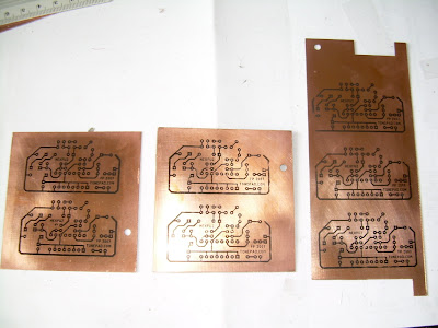
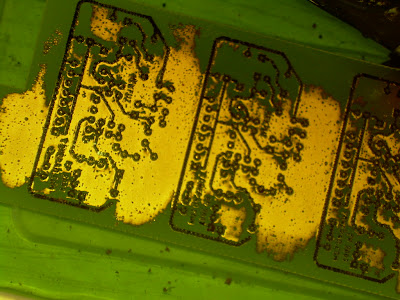
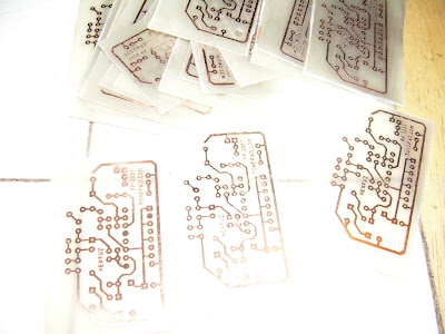
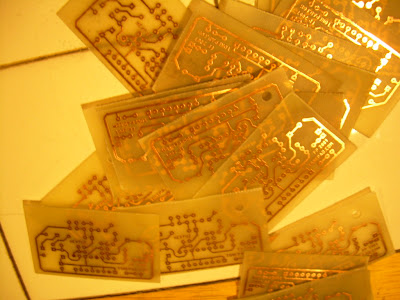
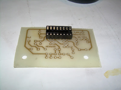
just to update, we have etched the pcbs for the first build. they are not all drilled yet but here are some pics from the process.


Monday, February 18, 2008

Red Llama Information

Hi

Since this is what has been selected for the group build here are some relevant links.

The tonepad file with schematic and pcb can be found here.

A similar circuit can be found on this page, if you scroll down to "Calavera"

and here are some user reviews from harmony central (the most credible review source).

Sunday, February 17, 2008

sample post...

Heres a picture of a pedal i made which is a clone of the ampeg scrambler.


more info here