Right, I'm going to give this blog thing a shot. A couple people have expressed interest in a couple of the pedals that were brought-in! The first of which was a feedback looper, the bypass looper that put all of the effects in its loop into crazy oscillating madness! It's a fairly simple project and doesnt involve any circuitry! If you've managed with the fuzz project or the ringmod, this will be a piece of cake! It's just a couple switches, wires, a potentiometer (and knob) and the enclosure of course. It's a great little box you can quickly build in-between workshops and have fun decorating!
Instructions for it can be found in this forum thread below. If you have any questions, you can email me as well.
thread on experementalistsanonymous.com
A couple other people have also expressed interest in that crazy 20-knob sequenced tremolo-thing! It should be considered more advanced, but I think I've compiled some good instructions. I should also warn that it doesnt work perfectly. There isa bit of ticking noise when its playing, and some values could be optimized, but at least it works! All parts can be found at Addisons. Again, if there are any questions abotu it, email me and I will do my best to answer!
voetsek_instructions_1.gif
voetsek_instructions_2.gif
voetsek_instructions_3.gif
voetsek_tremolo_diy_instructions.zip
Here are some photos from the first workshop
Posting Permission
If anyone who wants posting permission on this site please email me mtl.asm@gmail.com and i will add you
thanks
scott.
thanks
scott.
Saturday, July 19, 2008
Friday, July 18, 2008
fuzz face details
Hi
The following may help you complete your fuzz face.
First off as most people know from coming out last week, one of the transistors on the layout sheet is facing the wrong way. It is the p channel fet that was given out on that sunday. the orientation should be rotated 180 degrees. see the photos below.
Next up, germanium orientation. If you look closely at te bottom of the germanium transistors youll see the leads are not really in a straight row. instead they form abit of a triangle.
flip the board so that teh component side is facing you.
rotate the board so that the pots are in what you would consider the "lower right corner".
the input jack should be on the left and output on the right.
now populate the BOTTOM 3 PINS of the socket with germanium transistor such that the MIDDLE LEAD is closest to the RIGHT SIDE off the board. The orientation is the same for both germaniums.
Before the next step you may want to test your pedal to see how you like it. I spent some time with Maria's pedal and found the output was not that high and sort of nasaly sounding. The current gain of the transistors we have is not quite as high as the ones specified. but luckily it is easy to compensate. heres how.
Instead of a fine tuning mod we will use the trim pot as a large gain adjustment. Simply cut the trace from the output cap to the trim pot and solder a wire from the cap to the other side of the trim pot. Look at the photos.
Heres the mod on Maria's. ONLY AD THE YELLOW WIRE. teh other wires were added to replace lifted pads and may not be required. (definitely not required for the "mod")
Now play with the pot until your desired output level is achieved.
IF you still have questions please either make a post or make a comment. if you are confused it is likely other people will be too so it is more useful to ask in a forum accessible by everyone as opposed to through email. THANKS
The following may help you complete your fuzz face.
First off as most people know from coming out last week, one of the transistors on the layout sheet is facing the wrong way. It is the p channel fet that was given out on that sunday. the orientation should be rotated 180 degrees. see the photos below.
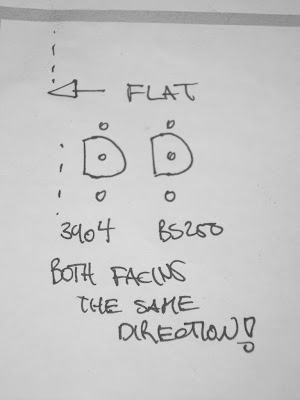
Next up, germanium orientation. If you look closely at te bottom of the germanium transistors youll see the leads are not really in a straight row. instead they form abit of a triangle.
flip the board so that teh component side is facing you.
rotate the board so that the pots are in what you would consider the "lower right corner".
the input jack should be on the left and output on the right.
now populate the BOTTOM 3 PINS of the socket with germanium transistor such that the MIDDLE LEAD is closest to the RIGHT SIDE off the board. The orientation is the same for both germaniums.
Before the next step you may want to test your pedal to see how you like it. I spent some time with Maria's pedal and found the output was not that high and sort of nasaly sounding. The current gain of the transistors we have is not quite as high as the ones specified. but luckily it is easy to compensate. heres how.
Instead of a fine tuning mod we will use the trim pot as a large gain adjustment. Simply cut the trace from the output cap to the trim pot and solder a wire from the cap to the other side of the trim pot. Look at the photos.
Heres the mod on Maria's. ONLY AD THE YELLOW WIRE. teh other wires were added to replace lifted pads and may not be required. (definitely not required for the "mod")
Now play with the pot until your desired output level is achieved.
IF you still have questions please either make a post or make a comment. if you are confused it is likely other people will be too so it is more useful to ask in a forum accessible by everyone as opposed to through email. THANKS
Subscribe to:
Posts (Atom)